Robust and Adaptive Active Control of Vertical Tail Buffeting
vertical tail buffeting · active vibration control · robust control · piezoelectric actuator · Smart Material P1 · PCB 333B30
Overview
This case targets low-order modal buffeting of a vertical tail structure. An RFxLMS multi-modal controller is proposed, applying feedback damping compensation to the secondary path. Macro Fiber Composite (MFC) piezoelectric actuators are used in both ground and wind tunnel experiments. ---
System Architecture
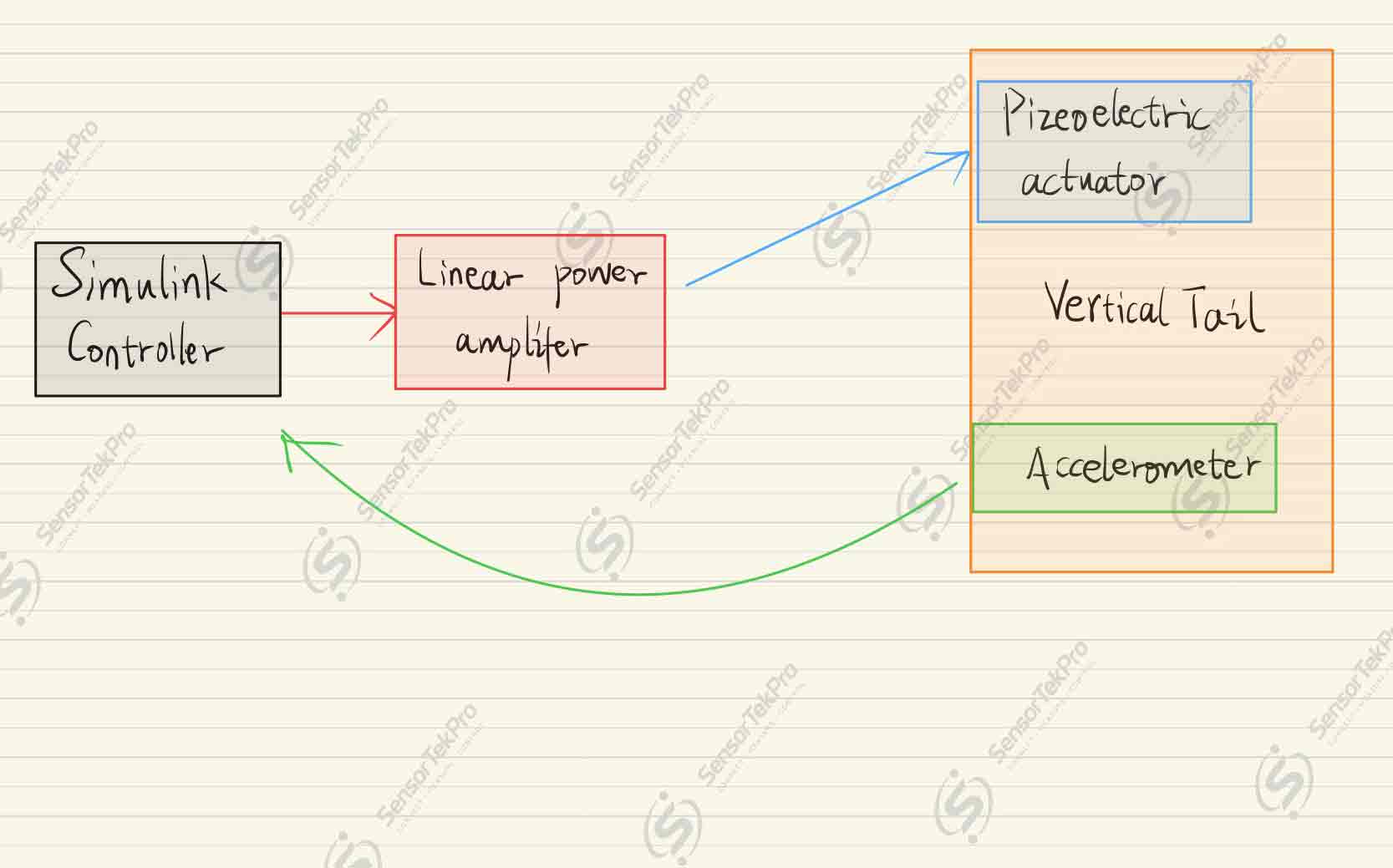
Signal flow summary: 1. **Controller** sends position command to the motor. 2. **Motor** receives command, rotates, and drives the hydraulic pump. 3. **Hydraulic pump** converts motor rotation into hydraulic flow and pressure. 4. **Hydraulic cylinder (actuator)** receives flow and produces displacement, pushing the load. 5. **Encoder on actuator** measures piston displacement, feeds back to controller. 6. **Pressure sensor on actuator** measures cylinder pressure, feeds back force information. 7. **Tank** stores hydraulic fluid and buffers pressure fluctuations. 8. **Tank pressure sensor** monitors fluid pressure to ensure system health and stability.
Experimental Setup
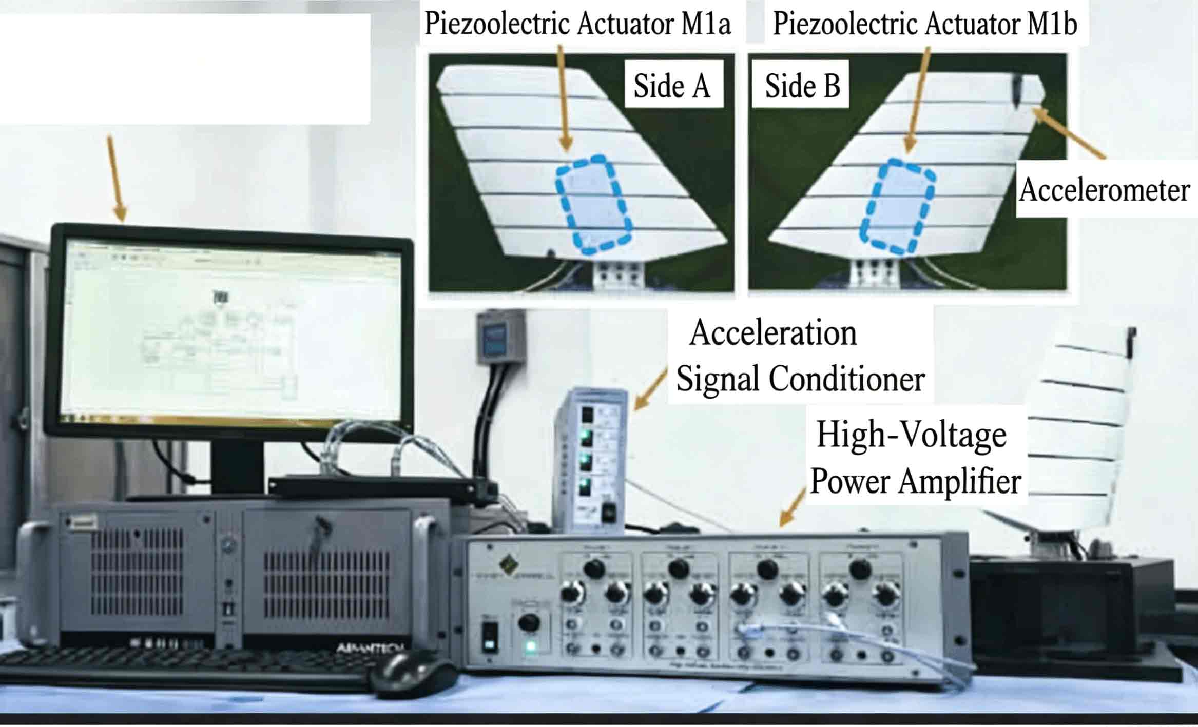
Hardware Configuration
| Component | Model |
|---|---|
| Piezoelectric Actuator | Smart Material P1 |
| Accelerometer | PCB 333B30 |
| High-Voltage Power Amplifier | Smart Material HVA 1500/50-4 |
Platform Compatibility Note
This system was validated under QUARC / Simulink. The signal interfaces (analog voltage, encoder, digital I/O) are electrically compatible with real-time control platforms including dSPACE, Speedgoat, and NI systems.
Applicable Scenarios
- Graduate research: active structural vibration control thesis experiments
- Aerospace: vertical tail buffet suppression ground and wind tunnel testing
- HIL simulation: multi-modal adaptive controller validation
- Control course labs: RFxLMS algorithm implementation with real piezoelectric hardware
Important Notice
This application example documents an actual lab setup and is provided for technical reference only. Hardware shown reflects the validated configuration used in this experiment; equivalent substitutions may be applicable for similar setups. Customers are responsible for final product selection and application suitability assessment.